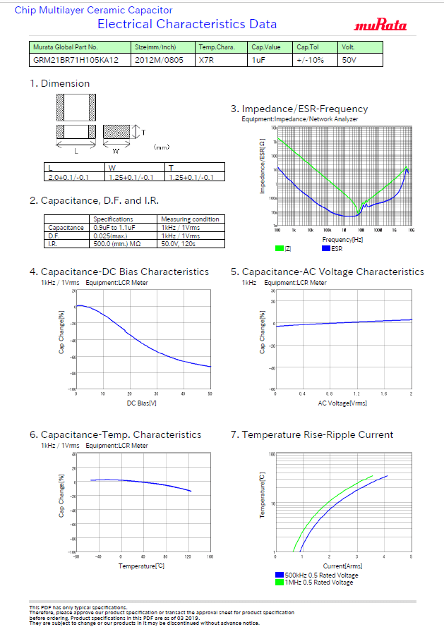
Temperature rise of the capacitor 0cthe temperature dif ference between the capacitor and the ambient. At steady state the rate of heat generation and heat removal balance so the two expressions can be set equal and we can solve for the temperature rise due to the ripple current heating.

Power Film Capacitors For Dc Bus Applications

Choosing A Capacitor Ripple Current Capability Matters As

Apec 2012 Slides Ipc 9592 Derating Guidance
Other factors that can reduce the expected life of a capacitor are.

Capacitor ripple current temperature rise. It is evident that a 100c temperature rise due to the esr will reduce the expected life by half. 2 ti esrrrms th 3. Hence vrms 2227mv.
The ripple current capability of a capacitor is one of the key parameters to consider when selecting a capacitor for a given application. Some specify the ripple capability at 100 khz. Dt is the temperature rise of the capacitor due to ripple current.
Care should be taken to limit the temperature rise tr due to the ripple current and esr to a maximum of 100c above the ambient temperature the capacitor is operating in. Others specify ripple capability from 100 khz through 1 mhz. This capacitors esr is 3246mw at 400khz suggesting the ripple current is 686a which is below the maximum for the device.
Choosing capacitors with low esr helps to minimize power dissipation and enhance the capacity of the circuit to withstand high ripple currents. Others allow a 400c rise. This current causes an internal temperature rise because of the power generated in the esr of the capacitor.
V o is the operating voltage of the capacitor. Table of base lifetime lb and maximum core temperature tm. In most capacitors ripple current and equivalent series resistance determines the temperature rise.
Some derive their data with a 200c temperature rise. Estimating lifetime for capacitors without an online calculator. This makes it difficult for end customers to have a one to one comparison.
In addition use a k thermocouple of o01mm with less heat capacity when measuring and measure in a condition where there is no effect from the radiant heat of other components or air flow caused by convection. Usually the voltage is applied at the capacitors rated temperature but other. The ac ripple current causes power dissipation and heating in capacitors.
Lifetime calculations for varying ambient temperature or varying ripple current. Rated ripple current symbol i r the ripple current at which the vendor specifies l 0. The load should be contained so that the self heating of the capacitor body remains below 200c when measuring at an ambient temperature of 250c.
Among the manufacturers catalogs some specify the ripple current capability at 250c others at 450c. Applied ripple current symbol i a the applied ripple current is the root mean square rms value of alternating current flowing through a capacitor. V r is the maximum voltage rating of the capacitor.
Eia ripple life test. In most capacitors the temperature rise is a function of ripple current and equivalent series resistance. The issue of ripple current can be challenging to analyze and to predict accurately under expected circuit operating conditions.
Capacitor heat up from its esr.

Power Tips How To Select Ceramic Capacitors To Meet Ripple

1 1 Precautions In Using Aluminum Electrolytic Capacitors

Power Tips How To Select Ceramic Capacitors To Meet Ripple

Ripple Cancellation With Low Esr Polymer Capacitors

Power Film Capacitors For Dc Bus Applications

Rf Amp Rating Of Ceramic Capacitors Electrical Engineering
Factors Affecting Temperature Rise In Mlc Capacitors

In Selecting An Input Capacitor Focus On The Ripple Current

Polymer Capacitor Wikipedia
Aluminum Electrolytic Vs Polymer Two Technologies
Aluminum Electrolytic Capacitor Application Guide

Product Information Aluminum Electrolytic Capacitor
Comments
Post a Comment