Capacitor Ac Phase Shift

When the capacitor is in parallel with a resistor the phase shift is only 45 degrees. The phase difference is 90 degrees.

Rc Circuits And Measuring Phase Angle

Rc Circuits And Measuring Phase Angle

Ac Capacitance And Capacitive Reactance In Ac Circuit

Ac Capacitance And Capacitive Reactance In Ac Circuit

Overview Of Impedance And Phases Of Rc Circuits For Ac

Overview Of Impedance And Phases Of Rc Circuits For Ac

It is customary to use the angle by which the voltage leads the current.


Overview Of Impedance And Phases Of Rc Circuits For Ac

Capacitor ac phase shift. Capacitors change the phase by 90 degrees. To get any phase shift there has to be some resistance in series either one you soldered in or the real internal resistance of your source. The fraction of a period difference between the peaks expressed in degrees is said to be the phase difference.

This video covers the basics of ac capacitive reactance including phase shift phasor diagrams and frequency. It merely absorbs and releases power alternately. As with the simple inductor circuit the 90 degree phase shift between voltage and current results in a power wave that alternates equally between positive and negative.

This means that a capacitor does not dissipate power as it reacts against changes in voltage. Share this video with the following link. Very large capacitor and resistor values result in a very low voltage across the capacitor which is almost 90 degrees out of phase with the powerline voltage.

Phase difference and phase shift phase difference is used to describe the difference in degrees or radians when two or more alternating quantities reach their maximum or zero values previously we saw that a sinusoidal waveform is an alternating quantity that can be presented graphically in the time domain along an horizontal zero axis. It is well known that there is a 90 deg phase shift between the current and voltage in the capacitor when supplied by a sinusoidal signal and it varies from 0 to 90 degrees in the rc integrating. The amount of phase shift of the voltage across the capacitor and its amplitude in relation to the powerline voltage is proportional the the values of the capacitor and resistor.

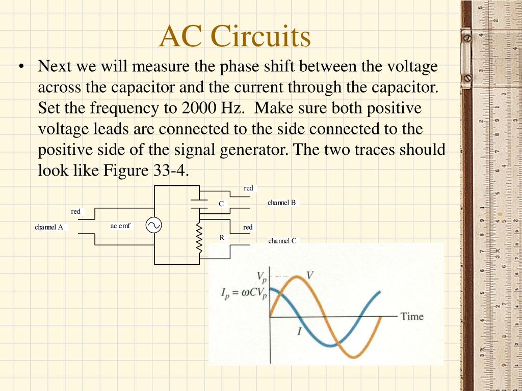
When capacitors or inductors are involved in an ac circuit the current and voltage do not peak at the same time. Therefore a phase shift is occurring in the capacitor the amount of phase shift between voltage and current is 900 for a purely capacitive circuit with the current leading the voltage. In a capacitive circuit the current leads the voltage.

You have to measure phase relative to some reference of course. A capacitor connected across it must follow that voltage. The opposite phase shift to an inductive circuit.

Learn About The Ac Phase Difference Eeweb Community

Learn About The Ac Phase Difference Eeweb Community

In A Series Rc Circuit 12 V Rms Is Measured Across The

In A Series Rc Circuit 12 V Rms Is Measured Across The

Transistor Phase Shift Oscillator Rc Phase Shift Network

Transistor Phase Shift Oscillator Rc Phase Shift Network

Masteringphysics Assignment Print View

Masteringphysics Assignment Print View

Solved Voltage And Current In Ac Circuits Learning Goal T

Solved Voltage And Current In Ac Circuits Learning Goal T

Polyphase System Wikipedia

Polyphase System Wikipedia

The Technology Of Phase Shifters And Flangers

The Technology Of Phase Shifters And Flangers

Rc Phase Shift Oscillator

Rc Phase Shift Oscillator

Ac Theory

Ac Theory

Motor Phase Shift Capacitor Components Lenco Heaven
Motor Phase Shift Capacitor Components Lenco Heaven

Ppt Ac Circuits Powerpoint Presentation Free Download

Ppt Ac Circuits Powerpoint Presentation Free Download

Phase Shift In A Rc Element Iamtechnical Com

Phase Shift In A Rc Element Iamtechnical Com

Comments

Popular posts from this blog

Capacitor Charging Formulas

The current alters the charge on a capacitor just as the flow of water changes the position of the membrane. They are the compliment of inductors which store energy in the form of a magnetic field. Dc Circuits Containing Resistors And Capacitors College Capacitor Charging Transient State Phy 124 Ac Circuits Stony Brook Physics Laboratory Manuals V is the voltage of the source. Capacitor charging formulas . The charging current asymptotically approaches zero as the capacitor becomes charged up to the battery voltage. Find the transient voltage across the capacitor using the following formula. Below is the capacitor charge equation. This gives the variation of charge across the terminals of capacitors as time varies where charge across the capacitor q the total charge that the capacitor can accumulate or the multiple of c v t time in seconds and

Capacitor Esr Values Table

Blog Of Tim Ashworth Characterizing High Q 100 Pf Aluminum Electrolytic Capacitor Design For Automotive Use Esr Capacitor Polymer Hybrid Capacitors Tapping Into Expertise At Its Choosing Between Ceramic And Tantalum Capacitors 31 Solved 5 Consider The Following Parameters When Using Cy Capacitor Lab Bob Parker Esr Low Ohms Meter From Evb Portugal Blog Of Tim Ashworth Characterizing High Q 100 Pf Table Of Typical Values Esps Esr Electrolytic Capacitors Esr Losses In Ceramic Capacitors Microwave Product Digest Ceramic Caps Vs Electrolytic What Are The Tangible Determining The Equivalent Series Resistance Esr Of

10k Ntc Thermistor Table

100k thermistor output table rev. 10k 2xp and 10k 3xp thermistors are typically stocked items all passive thermistors 10k w and smaller are ce compliant. Tutorial Better Thermistor Measurement On Arduino Via Thermistor Calculation Examples Ge Refrigerator Thermistor Temperature Resistance Data Table The resistance in 25 0c is 10k 1. 10k ntc thermistor table . For specific temperature to resistance check the lookup table. 10k 2 thermistor output table all passive thermistors 10k w and smaller are ce compliant. This epoxy coated precision 1 10k thermistor is an inexpensive way to measure temperature in weather or liquids. 750 north royal avenue gays mills wi 54631 usa. Where k is the negative temperature coefficient dt is the temperature difference and dr is the resistance change resulting from the change in temperature. An example of a thermist